Network Layout Guidelines
An Ethernet 10BASE-T system consists of either a header hub with several workstations connected to it, or a header hub with one or more intermediate hubs connected to it and to the workstations, in a star arrangement. Many variations of networks can be implemented using this system, as long as the 5 - 4 rule is not broken. The 5 - 4 rule simply states that between any two workstations there may be no more than five wire segments and four hubs. Adherence to this rule prevents excessive propagation delays (timing problems).
A wire segment includes all of the circuit elements that provide the physical electrical connection between workstations and hubs. For example, a wire segment can include drop cables, wall boxes, in-store wiring, jack panels, and patch cords.
Nominal Configuration
A nominal configuration may consist of a header hub, two intermediate hubs, one more hub off one of the intermediate hubs, and several workstations. Notice that the 5 - 4 rule is satisfied between workstations A and B.

Maximum Configuration
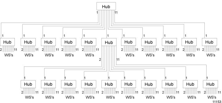
For a maximum configuration, if the header hub connects to eleven other hubs, each of those intermediate hubs can connect to up to ten other devices (since one of the eleven connections must be to a hub above it). One and only one of these secondary hubs may connect to another group of hubs.
These last hubs can only connect to workstations. Up to 200 workstations can be connected using this system. Notice that the 5 - 4 rule is satisfied between any workstation on the bottom row and any workstation on the top row.
Cabling
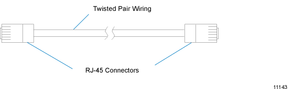
The hubs and workstations are connected using twisted-pair cables with RJ-45 connectors. The cable length between any two devices (hubs or workstations) cannot exceed 100 m (328 ft).
Note: These are connections from hub to hub or from hub to workstation. Workstations cannot be connected to each other except in a two-workstation system. In this situation, the transmit pair must be connected to the receive connections and the receive pair must be connected to the transmit connections at one end of the cable.
Combinations of cabling may be used.
| • | A drop cable from a hub to a wall box, twisted pair wiring from this wall box to another wall box near the destination, and a drop cable from the second wall box to a workstation or hub. This combination can contain connections through NCR cross connects in wiring closets. |

| • | A drop cable from a hub to an RJ-45 to RJ-45 adapter, an RJ-45 to RJ-45 cable from this adapter to another adapter near the destination, and a drop cable from the second adapter to a workstation or hub. |

An RJ-45 cable directly from a hub to a workstation or hub.
| • | Twisted pair wiring connections through NCR jack panels in wiring closets. |